
TRS 8 Channel Motor Controller
 TRS 8 Channel Motor Controller
2024 Specifications
The Rigging Shop 8 channel chain motor controller is a dedicated unit for the serial control of hoists. Although relatively simple in its operation, it should only be used by authorised persons competent enough to do so.
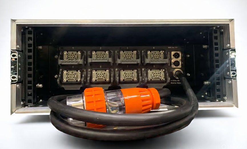
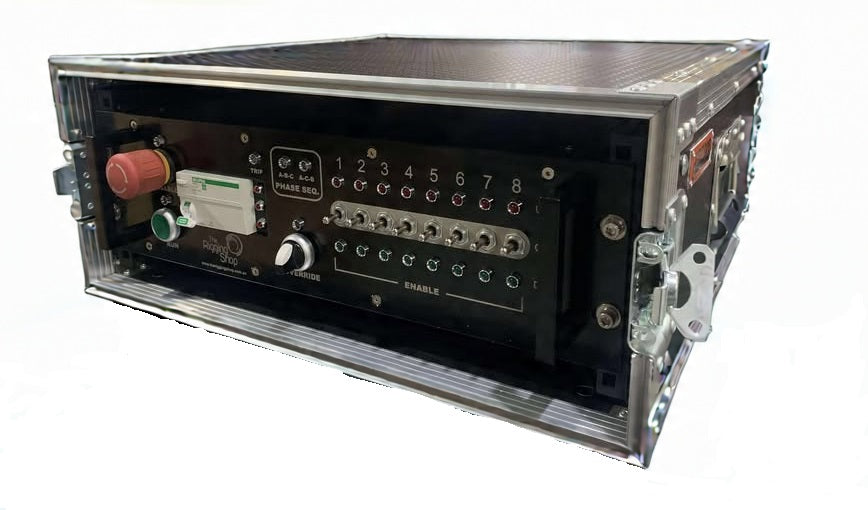
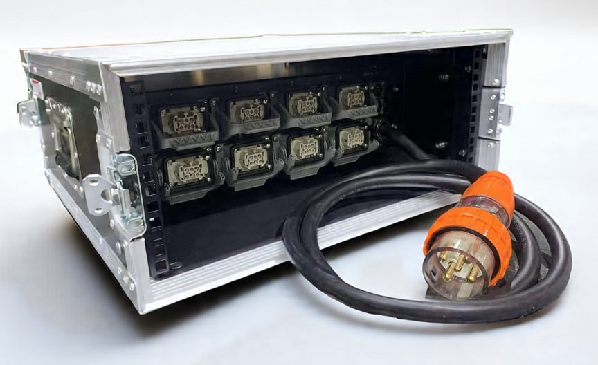
The controller is housed in a 3RU rack mount metal cabinet. A 4RU rack sleeve with lids is optional and strongly suggested to protect the controller. The rear, or connection side of the cabinet has 8 outlets for the motors, slave / master link connections and 3 phase mains supply input. The front panel is for control only. It comprises an RCD, individual channel selects, operate, override and emergency stop switches. Each has its own individual indication.
Connection
Mains supply is via a 32 amp 5 pole connection (415vac 50Hz). The chain motor power and control output are via 6 pole multi pin connectors numbered 1 thru 8. The master / slave function is standard in all our controllers and provides expansion of an 8-channel controller to operate multiple units simultaneously. Link connection is made via an optional 3 pin XLR cable. The ‘master controller’ is determined by the first MASTER OUT connection and controls the RUN and DISABLE functions of those units connected to it.
Operation
The incoming power supply is indicated by red phase lamps to the right of the RCD. These remain lit whilst connected to mains power, regardless of the RCD status.
An internal auto phase rotation relay is fitted as the power supply in venues may differ (it is important that motors run in the right direction in order not to bypass the internal limit switch of the motor). The power supply sequence is indicated by either the yellow ABC or ACB LED. This is extinguished when depressing the DISABLE button (RED), indicating that no power can be sent to the motors. Release the DISABLE button (GREEN) in order to return the controller to ‘standby’ mode.
A TRIP LED (BLUE) above the RCD indicates an overload of current from the motors and will inhibit power output from the controller until the problem is addressed. Once determined, and the problem rectified, the controller will reset on its own and operation can resume.
Mains power without control can be sent to the motors by turning the OVERRIDE switch to the right (GREEN). This function is for using local control (pickle) at the motor which is generally used for ‘floating’ motors in and out of their road cases or making rigging adjustments. The RUN and CHANNEL SELECT functions are unavailable in this mode and are only returned once OVERRIDE is switched off (RED).
Each hoist channel has a 3-position toggle switch to preselect UP, OFF, DOWN. Preselection is indicated by an LED above (RED) or below (GREEN) the corresponding switch. These lamps will be extinguished if DISABLE is activated (RED), indicating that hoist movement is unavailable. The toggles should be left in the OFF position when the controller is not in immediate use.
To operate the motors, ensure DISABLE is deactivated (GREEN), select the desired channels and direction and, when safe to do so, depress and hold the RUN button (GREEN) which then activates the selected motor or motors. Release the RUN button (RED) to cease movement. Be especially aware of any selected channels, particularly when other controllers are ‘slaved’ to the master unit.
The DISABLE switch, as it suggests, halts all output from the controller (and slaved controllers) in the unlikely event of any danger which may arise during the movement of the motors. All motors will stop immediately and cannot operate again until DISABLE has been reset and RUN initiated. This sequence should only resume once the operator is confident that the danger has been identified and safely eliminated. It is good practice to always DISABLE the controller when left unattended or between extended periods of use.
Indication
Red Neon - ON = mains power is present.
OFF = mains power not present.
Yellow LED - ON = mains phase sequence.
OFF = controller disabled.
Blue LED - ON = main contactor current trip.
OFF = main contactor OK
Multicoloured LED - GREEN = selection on
RED = selection off
OFF = selection unavailable
Channel Select LED - RED = channel selection UP
GREEN = channel selection DOWN
NONE = no channel selection
Connections
Mains input – Clipsal 56P532 Plugtop
Motor power / control output – Harting Han 6E 06 Female panel mount
Master out / Slave in – Amphenol XLR 3P Plug / Socket panel mount
The operator must be competent and completely familiar with the operation of the controller. They are responsible for the equipment being used correctly and should be fully instructed in its use, and aware of its operation including load limits. The Rigging Shop is available to instruct any operator on how to correctly use this equipment.
The purchaser indemnifies The Rigging Shop against any claims or actions in relation to the misuse of the controller or any equipment associated with its use, not excluding hoists, cabling or rigging equipment.